
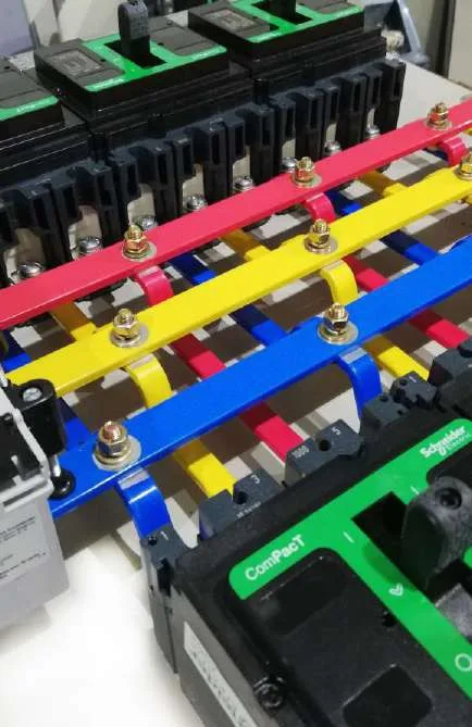
The busbar system carries the full current of a switchboard and has to survive the full force of a short circuit, so its rating comes from tested designs, not from a current-density rule of thumb. Material, finish, cross-section, support spacing and the torque on every bolted joint all decide whether it runs cool for twenty years or fails at a joint. Al Qudrah Switchgear in Sharjah, UAE uses tinned copper busbars on designs verified to IEC 61439-2 up to 3200 A and 65 kA for 3 s.
Why tinned copper?
Tin plating protects the copper surface from oxidation and corrosion, which keeps the contact resistance of bolted joints low and stable over time. Bare copper slowly forms an oxide layer, especially in humid or salty air.
That matters in the UAE, where many electrical rooms are near the coast and humidity is high for much of the year, and where air conditioning can fail in summer. A joint whose resistance rises gradually runs hotter, which speeds up oxidation, which raises resistance further. Tinning slows that cycle down. It also makes joints between busbars and device terminals more consistent, because tin is softer than copper and fills small surface irregularities when the joint is tightened.
Copper rather than aluminium is the norm for LV switchboard busbars in the region, because it carries more current per cross-section, makes more reliable bolted joints and is what most specifications ask for.
How are busbars sized?
Busbar size must come from the temperature-rise verification of the switchboard design, for the actual enclosure, ventilation, IP rating and ambient. A simple current-density figure does not account for those conditions and can be badly wrong in a sealed, hot board.
The same copper bar carries different currents depending on whether it is horizontal or vertical, painted or bare, in free air or in a closed compartment, and whether several bars are stacked with gaps between them. IEC 61439 requires the rated current to be verified, by test for larger assemblies, or by calculation or comparison with a tested reference design within the limits the standard allows. For main boards in our range, the busbar ratings come from the DEKRA and ASTA (Intertek) tested designs, verified at 50 °C ambient.
We also use Legrand XL PRO³ for layout and heat dissipation on XL³ boards. For a board running in a hot UAE electrical room, the verified ambient is as important as the cross-section.
Supports and short-circuit forces
During a short circuit, the magnetic forces between busbars rise with the square of the peak current, so a 143 kA peak produces forces several times higher than a lower fault. Busbar supports, their spacing and the bar cross-section must hold the bars in place under those forces.
This is why the support spacing in a tested design should be followed exactly. Moving supports further apart to fit a cable or a device can turn a verified design into an unverified one. Support material must also keep its strength at the temperatures the bars reach, and maintain creepage distances after years of dust and humidity.
| Design element | What controls it |
|---|---|
| Cross-section and number of bars per phase | Rated current, verified by temperature-rise test or permitted method |
| Support type and spacing | Peak short-circuit current (Ipk) from the tested design |
| Phase spacing | Clearances, creepage and short-circuit forces |
| Finish | Tinned copper for stable joints; sleeving or insulation where specified |
| Neutral size | Load type and harmonic content |
| Earth (PE) bar | Fault current and protective conductor requirements |
Sizing the neutral
On modern building loads, the neutral can carry as much current as a phase, or more. Third-harmonic currents from single-phase electronic loads add up in the neutral instead of cancelling.
LED lighting, computers, UPS systems and other single-phase electronic loads produce triplen harmonics. In buildings dominated by these loads, a half-size neutral is a risk. Many specifications now ask for a full-size neutral on main and sub-main busbars, and some ask for an oversized neutral where harmonic content is high. The consultant decides, based on the load type; the busbar system must then be verified with that neutral.
Why joint torque matters
A bolted busbar joint only performs as tested if it is tightened to the specified torque. Too loose and contact resistance rises, so the joint overheats; too tight and the bolt stretches or the copper deforms, and the joint loosens later.
We tighten every joint to the switchgear system's torque table with calibrated torque tools, using the bolts and washers the system specifies, and then mark it. The torque mark, a paint line across the bolt head and bar, shows at a glance during inspection that the joint was checked and has not moved since. Where needed we check joint resistance with our 150 A millivolt-drop tester, which shows a poor joint as a higher voltage drop than its neighbours.
On site, joints disturbed for transport splits or cable termination must be re-torqued. Thermal imaging under load after energisation is a good final check. More about our testing is in routine tests before dispatch.
Busbar systems at a glance
- Tinned copper keeps joint resistance stable in humid UAE conditions.
- Ratings come from verified designs for the real enclosure, IP and ambient.
- Support spacing is set by short-circuit peak forces and must follow the tested design.
- Neutral size depends on harmonic content; full-size is now common.
- Every joint should be torqued with calibrated tools and marked.
Our MDB busbar systems are horizontal and vertical tinned copper, sleeved and colour-coded, and drilled for future extension. See the main distribution boards page for the full ratings.
Frequently asked questions
Why are switchgear busbars tinned?
Tin plating protects copper from oxidation and corrosion, which keeps the resistance of bolted joints low and stable over the life of the switchboard. This matters most in humid or coastal environments such as the UAE. Tin is also slightly softer than copper, so it helps the joint surfaces make good contact when the bolts are tightened.
Can busbar size be calculated from current density alone?
No. Current density ignores the enclosure, ventilation, IP rating, bar arrangement and ambient temperature, all of which change how hot the busbars run. IEC 61439 requires the rated current to be verified by test, or by calculation or comparison within the limits the standard sets. For main boards, use busbar ratings from a tested design at your expected ambient.
Should the neutral busbar be full size?
On most modern buildings, yes. Single-phase electronic loads such as LED lighting, IT equipment and UPS systems produce third-harmonic currents that add up in the neutral. A half-size neutral can overheat. The consultant decides the neutral size from the load type, and some specifications call for an oversized neutral where harmonics are high.
What is a millivolt-drop test on busbars?
A millivolt-drop test passes a known DC current, for example 100 A or more, through a joint or contact and measures the voltage across it. From that, the contact resistance is calculated. A joint with higher resistance than similar joints indicates poor tightening or contamination. Al Qudrah uses a 150 A millivolt-drop tester for this check.