
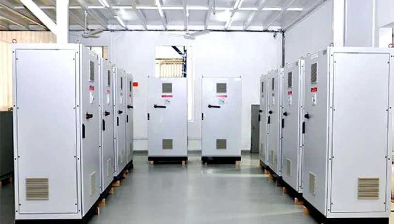
A capacitor bank corrects power factor by supplying the reactive power that motors, transformers and other inductive loads need, so the utility supply and your cables no longer have to carry it. The result is lower current for the same useful power, which cuts cable and transformer losses, frees capacity and helps meet any power factor requirement in the supply terms. Al Qudrah Switchgear in Sharjah, UAE builds automatic capacitor banks set to a target cos φ of 0.94, and this article explains how they work and how to size one.
What is power factor and why does it fall?
Power factor is the ratio of real power (kW) to apparent power (kVA). It falls below 1 when loads draw reactive power to build magnetic fields, which is what induction motors, fans, pumps, chillers and transformers do.
Reactive power does no useful work, but it still flows through the transformer, the MDB and every cable on the way to the load. A building with a power factor of 0.80 draws 25% more current than the same load at 1.0. That extra current heats cables and transformers and uses up capacity that could be serving real load.
UAE buildings with large air-conditioning loads are typical cases. Compressors, fan motors and pumps running at part load often have a lower power factor than at full load, so the building's overall figure can drop in the evening or in cooler months.
How do you calculate the capacitor bank size?
The kvar required equals the real power multiplied by the difference between the tangent of the existing angle and the tangent of the target angle: Q = P × (tan φ1 − tan φ2). You need the load in kW, the existing power factor and the target.
A worked example: a building with a 500 kW demand at a power factor of 0.80, corrected to 0.94.
- At 0.80, tan φ1 = 0.75.
- At 0.94, tan φ2 ≈ 0.363.
- Q = 500 × (0.75 − 0.363) ≈ 194 kvar.
In practice we would offer a 200 kvar bank split into steps, after checking the load profile. For a new building, the consultant estimates the kW and power factor from the load schedule. For an existing site, a few days of logging with a power analyser at the MDB gives far better numbers, and it also shows whether harmonics are present, which decides whether the bank needs reactors.
What does correction actually save?
The direct saving is in current. Raising the power factor from 0.80 to 0.94 reduces the current for the same kW by about 15%, and because resistive losses vary with the square of current, cable and transformer copper losses fall by roughly 28%.
| Power factor | kVA for 500 kW | Current at 415 V | Relative copper losses |
|---|---|---|---|
| 0.80 | 625 kVA | about 870 A | 100% |
| 0.90 | 556 kVA | about 773 A | 79% |
| 0.94 | 532 kVA | about 740 A | 72% |
The second saving is capacity. A transformer serving 625 kVA of load at 0.80 can serve the same kW at 532 kVA once corrected, leaving room for extra load without replacing the transformer or the MDB incomer. Voltage drop along long feeders also improves.
Whether there is also a direct tariff saving depends on the utility and the type of connection. Some supply terms set a minimum power factor or charge for reactive energy, and many consultant specifications set a design target. Check the specific requirement with the consultant and the utility for your site.
How an automatic capacitor bank works
An automatic bank uses a power factor regulator that measures current and voltage at the incomer and switches capacitor steps in and out to hold the target. Each step is a capacitor group switched by its own contactor and protected by fuses or an MCCB.
The details that make a bank last:
- Capacitor-duty contactors with damping resistors limit the inrush current when a step is switched in.
- Discharge resistors bring each capacitor's voltage down before the step can be switched again. The regulator's step time has to allow for this; we set ours to 40 s.
- Step sizes are chosen so the regulator can follow the load closely without hunting. A mix such as 25 and 50 kvar steps is common.
- Ventilation with thermostat-controlled fans keeps capacitors within their temperature class. Heat shortens capacitor life, which matters in UAE electrical rooms.
- The current transformer for the regulator must sit upstream of both the load and the bank, on the correct phase. A CT in the wrong place is the most common commissioning fault.
Low-voltage power factor correction assemblies are covered by IEC 61921, and the self-healing capacitors inside by IEC 60831. Our banks are set to cos φ 0.94 with a 40 s step time as standard, adjusted where the consultant specifies otherwise. You can see the range on our capacitor bank panels page.
Standard or detuned bank?
Use a standard bank only where harmonic distortion is low. Where variable speed drives, UPS systems, LED lighting or other non-linear loads produce significant harmonics, a standard bank can resonate with the network and fail early, so a detuned bank with series reactors is needed.
We fit 7% detuned reactors where measurements or the load mix show that harmonics require them. The reasons and the numbers are in our article on detuned capacitor banks and harmonics.
Frequently asked questions
What power factor should a capacitor bank target?
Most specifications target between 0.90 and 0.95. Al Qudrah sets its automatic banks to cos φ 0.94 as standard, which gives most of the available loss reduction without risking over-correction at light load. Correcting to exactly 1.0 is rarely worth it, because the last few percent cost a lot of kvar and the bank can push the power factor leading.
How do I know how many kvar I need?
Use Q = P × (tan φ1 − tan φ2), where P is the real power in kW, φ1 the existing angle and φ2 the target. For example, 500 kW at 0.80 corrected to 0.94 needs about 194 kvar. For existing buildings, log the MDB with a power analyser for several days first so the bank matches the real load profile.
Why does a capacitor bank need a step delay?
A capacitor that has just been switched off still holds charge. Switching it back on before it has discharged can cause a large current surge that damages contactors and capacitors. Discharge resistors bring the voltage down, and the regulator's step time gives them time to work. Al Qudrah sets a 40 s step time on its banks.
Can a capacitor bank be added to an existing MDB?
Usually yes. The bank is a separate panel fed from a spare feeder on the MDB, sized for the bank's current with margin for harmonics. The regulator's current transformer is installed on the MDB incomer. Before choosing a standard or detuned bank, measure the existing harmonic levels at the MDB.