
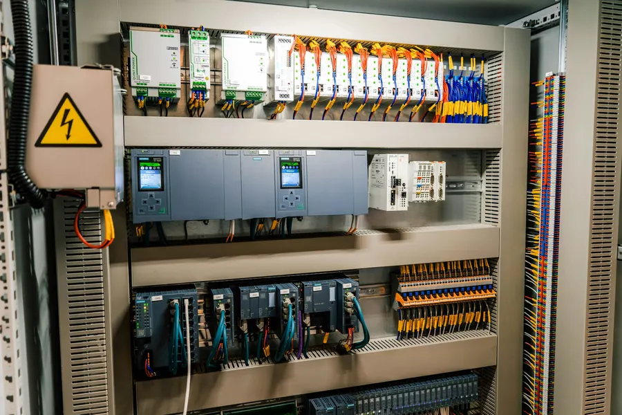
A PLC and SCADA control panel project runs in six stages: a clear control philosophy, an agreed I/O list, panel design, programming, a factory acceptance test, and site commissioning. Most problems on site trace back to the first two, not to the hardware. Al Qudrah Switchgear in Sharjah, UAE designs, builds and programs PLC, HMI and SCADA panels in house, and this is the process we follow.
Stage 1: the control philosophy
The control philosophy, sometimes called the functional description, describes in plain language what the system must do in every operating state. It is the document everyone tests against later, so it is worth getting right first.
A useful control philosophy covers normal operation, start-up and shutdown sequences, duty and standby rotation, what happens on each alarm and trip, what happens after a power failure, manual and maintenance modes, and what the operator can change. It should be written by or with the process owner, not left for the programmer to guess.
For a booster pump set that might be one page. For a crusher line, a cement batching plant or a bagging line, it can run to dozens. Either way, a clause like "the system shall operate automatically" is not a control philosophy.
Stage 2: the I/O list and communication schedule
The I/O list names every signal into and out of the PLC: digital inputs and outputs, analogue inputs and outputs, and their ranges, sources and destinations. It drives the hardware selection, the panel size and the programming.
We recommend 15 to 20% spare I/O unless the specification says otherwise, because new signals always appear during commissioning. Communication points belong in their own schedule: Modbus RTU or TCP registers from VFDs and meters, BACnet or Modbus points to the BMS, Profinet or other fieldbus links to remote I/O. Agreeing the register maps early avoids the classic site problem of two systems that both "support Modbus" but cannot read each other's data.
Stage 3: hardware and panel design
Hardware is selected from the I/O list, the environment and the client's preferred brands, then the panel is laid out and drawn. In the UAE, heat is often the deciding design factor.
- PLC and I/O sized for the signal count plus spares, with the CPU and memory headroom for future logic.
- A UPS or DC buffer so the PLC and network survive short supply interruptions and log the event.
- Segregation of power, control and signal wiring, with screened cables for analogue and communication circuits.
- Surge protection on incoming supplies and on field signals that run outside.
- Heat calculation including VFDs, power supplies and the sun on outdoor panels, followed by the right fans, filters or panel air conditioner.
- Clear terminal numbering that matches the drawings, and ferrules on every wire.
We design in EPLAN so schematics, terminal plans and cable schedules come from one model. The panel itself is assembled and wired in our 1,500 m² factory in Emirates Industrial City.
Stage 4: programming and HMI or SCADA screens
Programming turns the control philosophy into PLC logic and operator screens. Structured, commented code and consistent tag names matter as much as the logic, because someone will maintain it for years.
Our engineers program PLCs, HMIs and SCADA in house. We build screens around how operators actually work: an overview page showing the plant state at a glance, detailed pages per unit, alarm lists with time stamps and acknowledgement, trends for the variables that matter, and clear indication of which equipment is in manual. Alarm text should say what happened and where, in words the operator will understand at 3 a.m.
Stage 5: factory acceptance test
The FAT proves the panel and the program before they reach site, where faults cost far more to fix. The client or consultant should witness it against a written test procedure.
A good FAT for a PLC panel covers:
- Electrical routine tests: visual and mechanical inspection, insulation resistance at 1000 V DC on power circuits, the dielectric test and function tests of power and control circuits.
- Point-to-point I/O check: every input simulated at the terminal and seen on the HMI, every output forced and checked at the terminal.
- Sequence tests with simulated field signals, following the control philosophy step by step, including alarms, trips and power-failure recovery.
- Communication tests with any devices available, or with a simulator using the agreed register maps.
Every panel leaves with a signed factory test certificate. Our article on routine tests and witnessing a FAT covers the electrical side in more detail.
Stage 6: site testing and handover
Site commissioning repeats the I/O check with real field devices, tunes the control loops under real conditions, and proves the full sequence with the plant running. Handover documents close the job.
On site, expect wiring to field devices to account for most faults: swapped signals, reversed analogue polarity, or devices set to a different range than the I/O list. PID loops for pressure, temperature or level are tuned with the actual process. The handover pack should include as-built drawings, the final program with comments, the I/O list, the communication point list, the operation manual and the commissioning records.
We have used this process on panels for crushers and cement plants, hydroponics, bagging lines, conveyors and building services, and on the master control panel for the Vida Dubai Mall heat pump plant, which combined PLC, HMI and BMS points. More on our automation work is on the PLC and SCADA page.
Frequently asked questions
What documents do I need before ordering a PLC panel?
At minimum, a control philosophy describing how the system should behave in every operating state, an I/O list with signal types and ranges, and a communication schedule if the panel will talk to a BMS, SCADA or drives. A specification for brands, enclosure, IP rating and environment completes the package. Without these, the panel builder has to guess, and guesses get fixed on site.
How much spare I/O should a PLC panel have?
A common allowance is 15 to 20% spare I/O on each signal type, plus physical space for extra modules. Commissioning and later operation almost always add signals. Spare capacity is cheap during manufacture and expensive to add later, when it may need a larger enclosure or a new rack.
What is tested at a PLC panel FAT?
The electrical routine tests on the panel, a point-to-point check of every input and output, and a functional test of the program using simulated field signals, following the control philosophy. Alarms, trips, manual modes and power-failure recovery should all be tested. Communication links are tested with real devices or a simulator.
Can Al Qudrah integrate a PLC panel with an existing BMS?
Yes. We provide BMS points from PLC panels over the protocol the BMS uses, commonly Modbus or BACnet, or as hardwired signals where the BMS requires them. The point list and register map should be agreed with the BMS contractor early, so both sides program to the same addresses and data types.